
Frequency counter 10k - 1,2GHz
| Schematics: | Meter | Power Supply | |
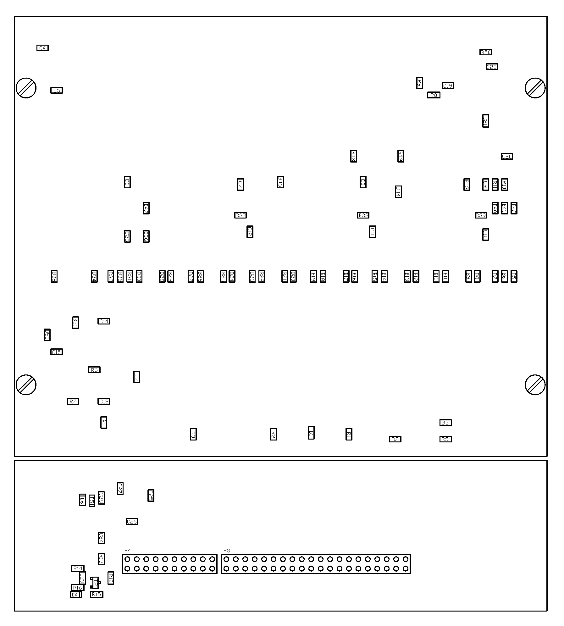
| PCBs (GIF): | Tracks | Assembly-top | Assembly-bottom |
| PCBs (PDF): | Tracks | Assembly-top | Assembly-bottom |
| PCBs (Post Script): | Tracks | Assembly-top | Assembly-bottom |
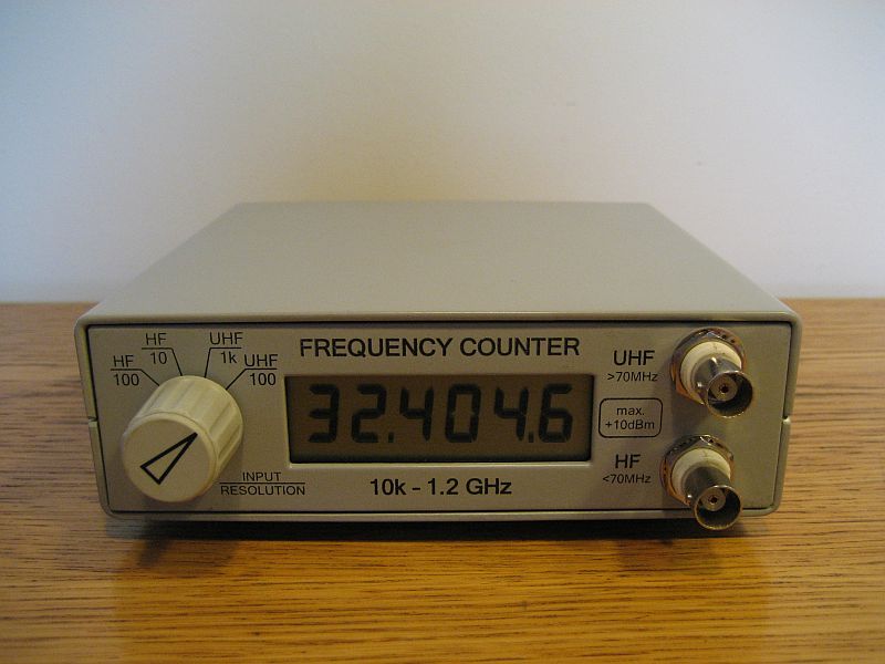
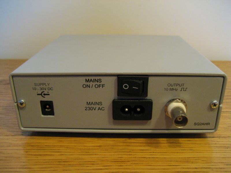
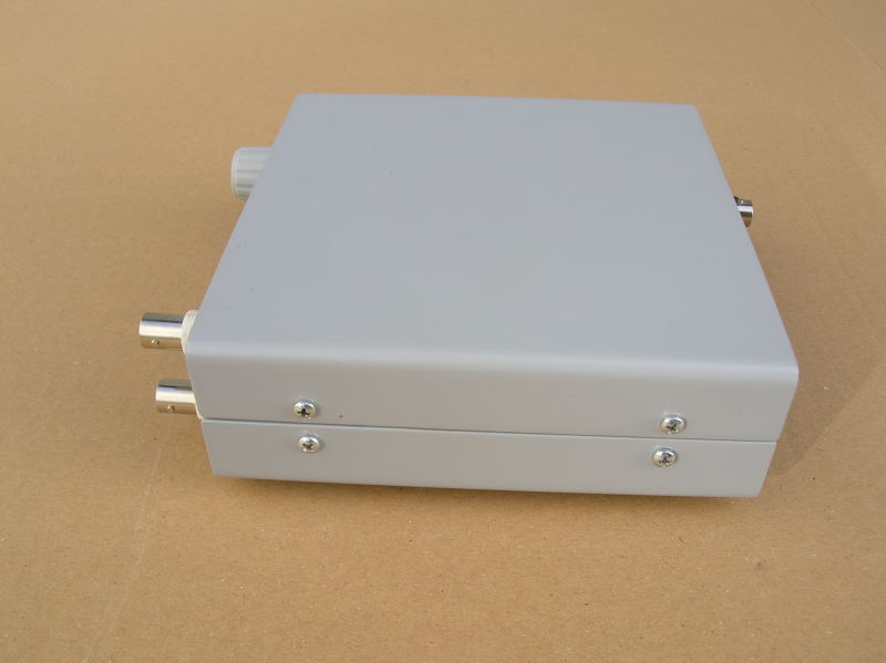
| Enclosure: | Front | Back | Side |
| Inside: | Up | Down | Side | Mechanics: | Supports | Front | Back | Down | Up |
| Calibration: | Calibration |
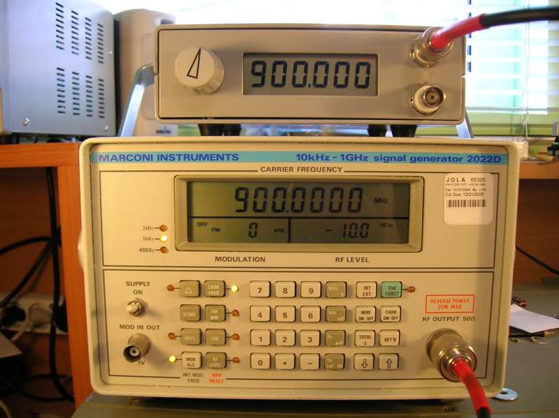
NOTE: This project and article below are from 2006. I would design it differently now...
The frequency counter is based on previous experiences in using and building of such equipment (professional and amateur). I noticed that there are some features that a good counter must have:
- refresh rate as fast as possible (limited only by time base and prescaler divide ratio),
- input prescaler reseted periodically in every measuring cycle (no jumping numbers on the last digit),
- high stable frequency standard (measurement precision depends on it),
- easy readable display with fast response (LED) and possibility to work in bright conditions (LCD),
- "stable" enclosure for desk use,
- internal power supply unit (230V), input for external DC supply (field operation).
The frequency standard is the heart of every frequency counter. The most common mistake made, not only in amateur equipment, is building multistage (6-8) counter and a time standard made of inverter gate and simple quartz resonator with some ceramic capacitors (not NP0). Such generator can have as much as 30 ppm instability, so while measuring 1GHz signal the mistake can be 30kHz (!!!). Using only 3 stage decade counter (100kHz precision) makes the mistake invisible, but for 6 decades the half of the result is false! Always look on the time standard stability before you buy some equipment.
The other problems with time standards are temperature range and the startup time (from turn on to full stability). Good counters have these parameters specified. The OCXO standards (heated) has higher stability but also has higher deviation at the beginning (cold) - I have observed startup deviation as big as 100 ppm (!!!). Also, TCXO (temperature compensated) standard needs some time for startup. From these observations come one conclusion - always heat up the counter before you start your measurements (for at least 15 minutes) and don't turn it off for the rest of the day :-)
My counter has following parameters:
- measuring range 10kHz - 1,2GHz in 2 bands (different inputs): HF 10kHz-70MHz; UHF 70MHz-1,2GHz
- 4 time bases (resolution: HF 100Hz/10Hz; UHF 1kHz/100Hz),
- input sensitivity better than 30mV (-17dBm) @ 50R,
- refresh rate for HF band limited only by input resetable prescaler (divide by 4),
- refresh rate for UHF band limited by input prescaler (divide by 64, but not resetable) and resetable prescaler (divide by 4, the same as for HF, used for stabilising the results)
- LCD 7-segment display (faster response than alphanumeric LCDs),
- 1 ppm 10MHz TCXO standard (Geyer),
- metal enclosure,
- built in power supply (230V), input for 10-30V DC,
- buffered 10MHz time base signal output.
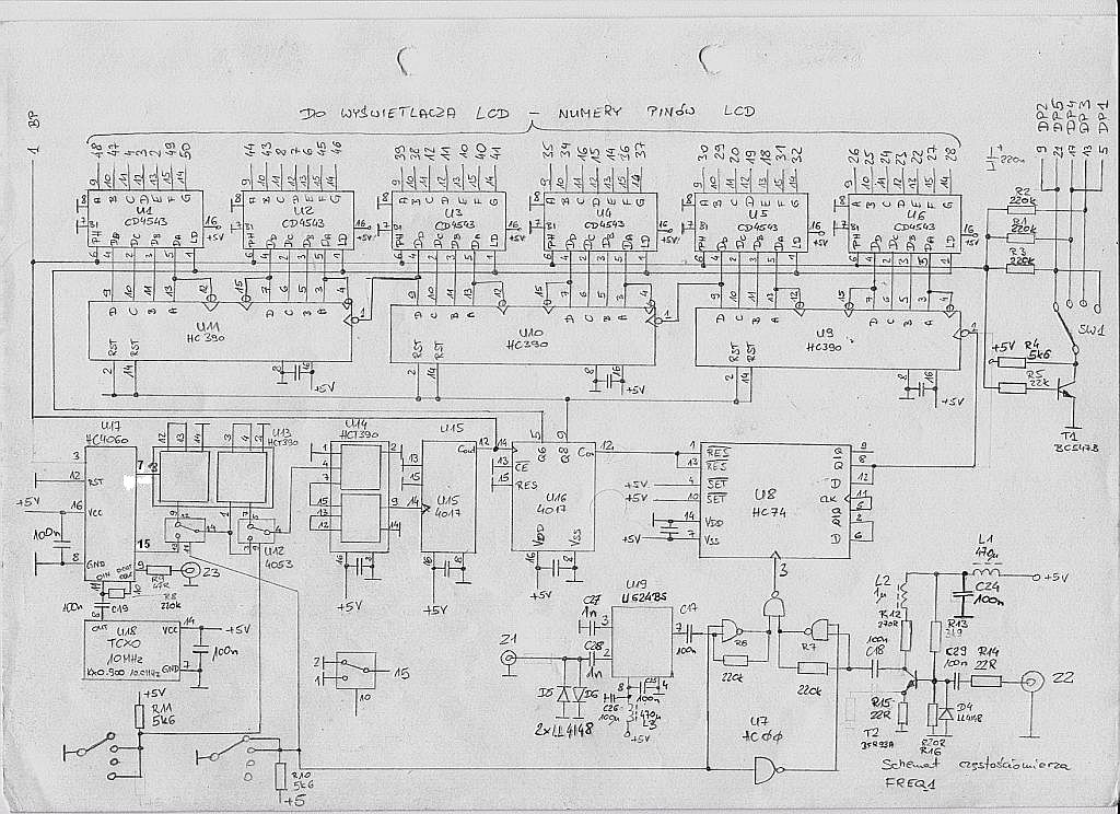
The counter has two inputs separate for HF and UHF band, selected by position of the time base switch. The first stage in HF input is the broadband preamplifier built around BFR93A (Ic=5mA), followed by a linear gate HC00. This duo works great from few kHz to 74MHz giving the sensitivity from 5mV (-33dBm) @ 1-50MHz to 50mV (-13dBm) at the end of bandwidth. The UHF input goes directly to the input prescaler (divide by 64) made on strange and obsolete U624 (the same pins as U664) from Telefunken. This prescaler is made in ECL logic so a level converter should be used to go into CMOS/TTL logic, but since the output is never quiet (even if there is no input signal, prescaler oscillates itself) and the level is about 1Vpp I used a capacitor coupling and a linear gate. The input is selected by a gate multiplexer build on HC00 - note that gates used for inputs work in the linear mode having huge gain (about 20dB). The output signal goes to the resetable prescaler (divide by 4) build on HC74 - it works to 74MHz using standard HC series in DIL14 case. Next, the divided signal goes to the 6 stage decade counters made on HC390 and to the latch/decoders for LCD display (4543). For proper LCD driving, decoders need a also clock signal. The LCD manufacturer writes that it should be 32Hz (optimal), but it can vary lot. First I tried about 600Hz from the last timebase divider but it is too high and the display gets fuzzy (bad contrast), so I decided to use a time base signal which will vary according to the actual time base setting, but works ok - the LCD clock vary from 4Hz (little flatter is seen from some angles) to 50Hz. Inverter made on NPN transistor was used to make 180 phase shift signal used for driving LCD dots by one section of the time base switch.
The most important half of the unit is the time base standard and dividers generating all required control signals (input gating, latch, reset). I used available and not expensive (11$) 1ppm 10MHz TCXO from Geyer. It is again coupled by a capacitor with 4060 divider - note that the input gate of the divider used normally for XTAL generator works in linear mode - the signal from TXCO is not TTL, it is almost sine wave (2Vpp). The divided signal goes through HC390 (divide by 100), multiplexer 4053 selecting the right time base, 4017 (divide by 10) and next 4017 making all control signals.
HC74 was used for gating the input signal. While RESET signal gets active (logic 0), input CLOCK signals will not affect the output (is gated).
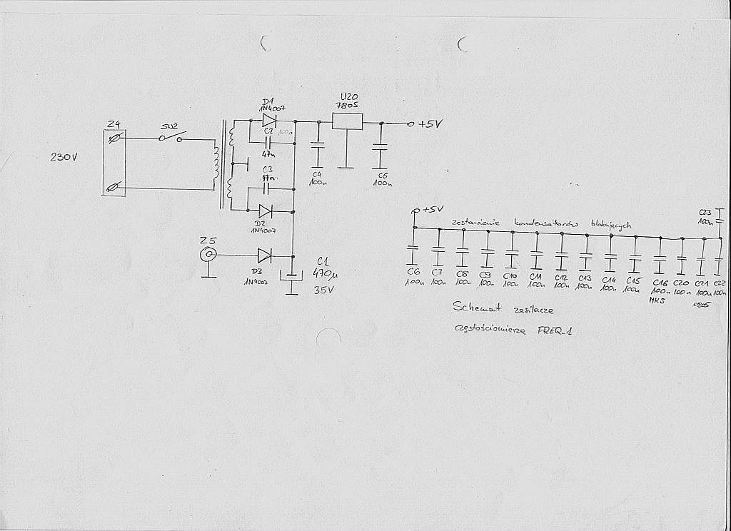
Power supply is classical linear one. Current consumption is about 80mA (most of it takes U624) @ 5V. The 7805 stabiliser has its heat sink connected to the Alu chassis, so you can power it with 30V DC :-)
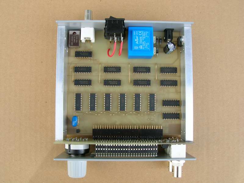
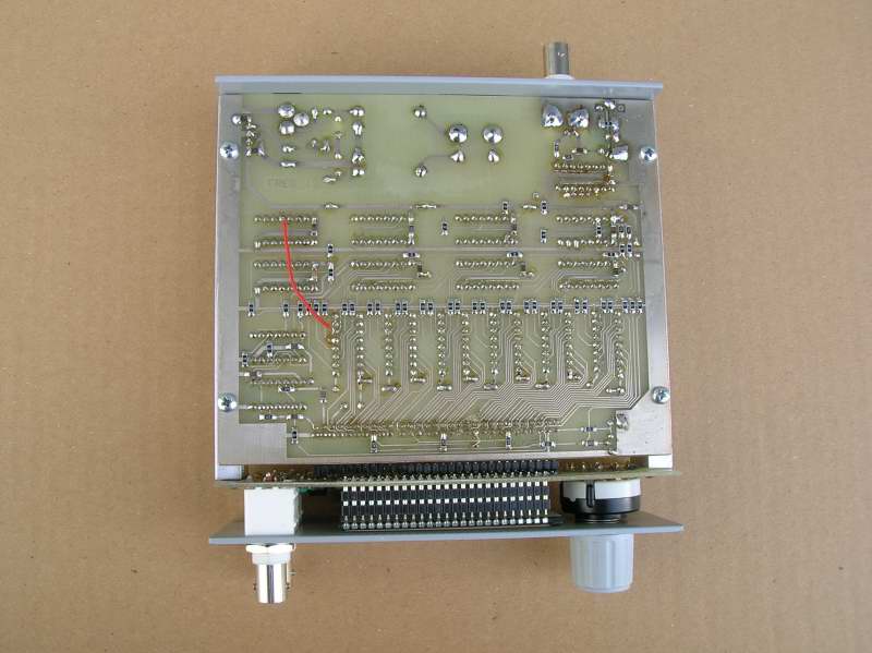
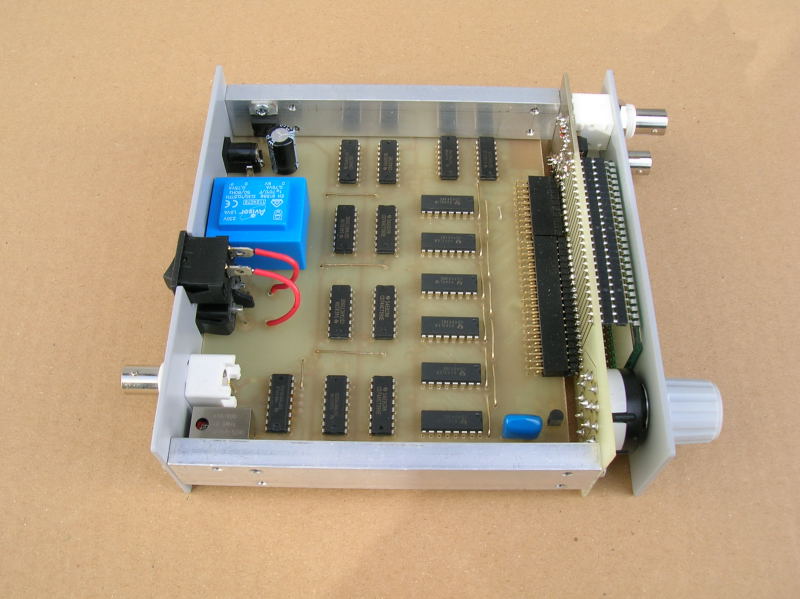
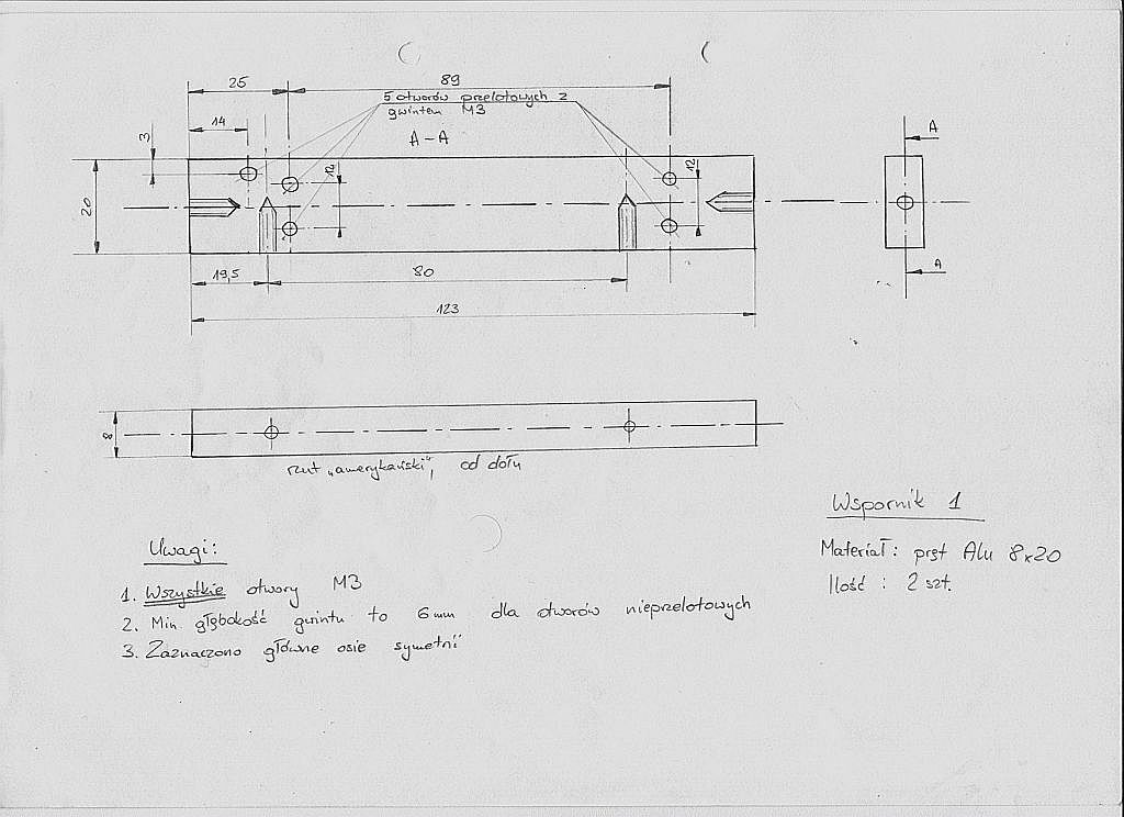
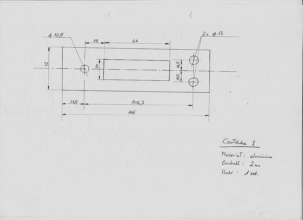
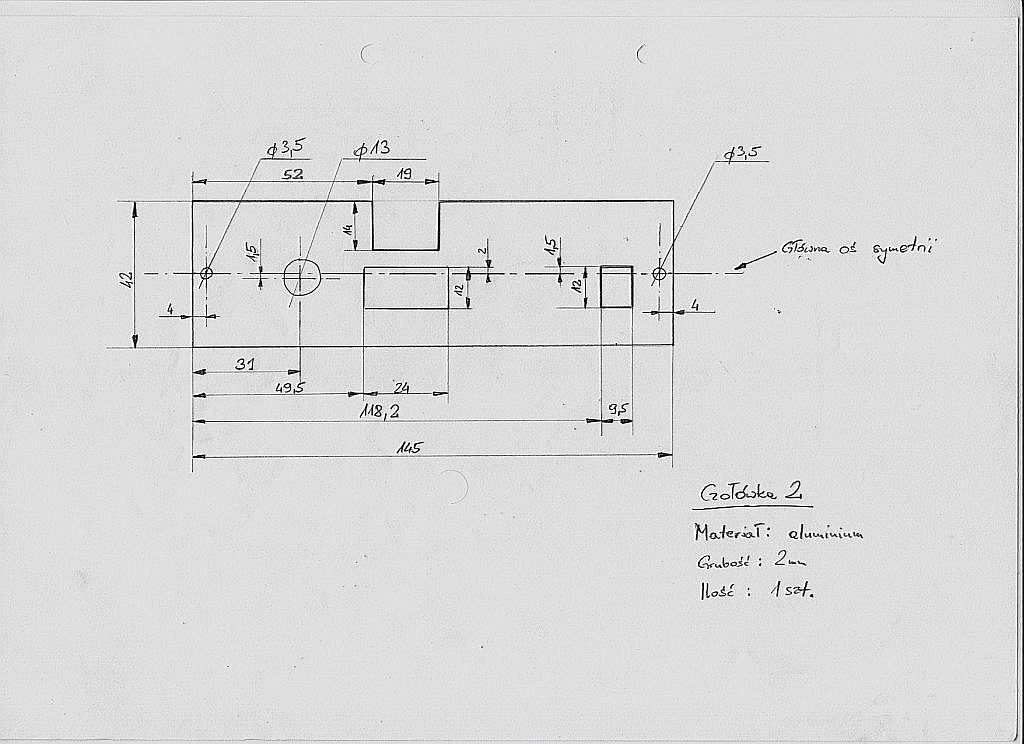
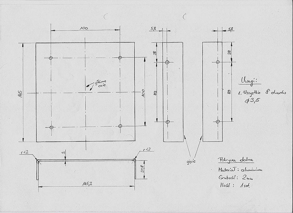
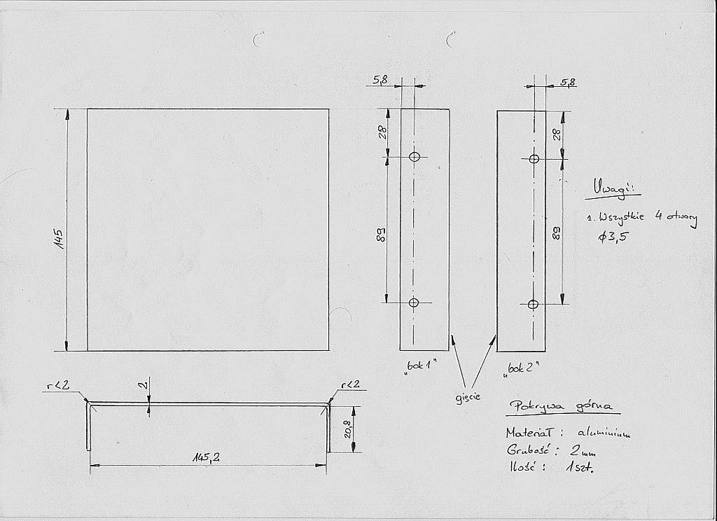
The metal enclosure was made according to the mechanical drawings by a local mechanic shop.
At the end I have to answer one question: "Why did I do it using CMOS and not microcontroller???"
The possible answers are: there won't be any problem at some "cosmic" combination of input data, the enclosure had to have such dimensions and there would be more air than electronics inside :-); most of the microcontroller counters that I used had terrible refresh ratio - they were too slow to me; almost equal price (most of the price is not connected with CMOS ICs); challenge :-)
This idea was born because of the lack of good counter in reasonable price that would fit my preferences. I use it quite often and it works as supposed.